How to Specify Tolerances for Machining Die Castings
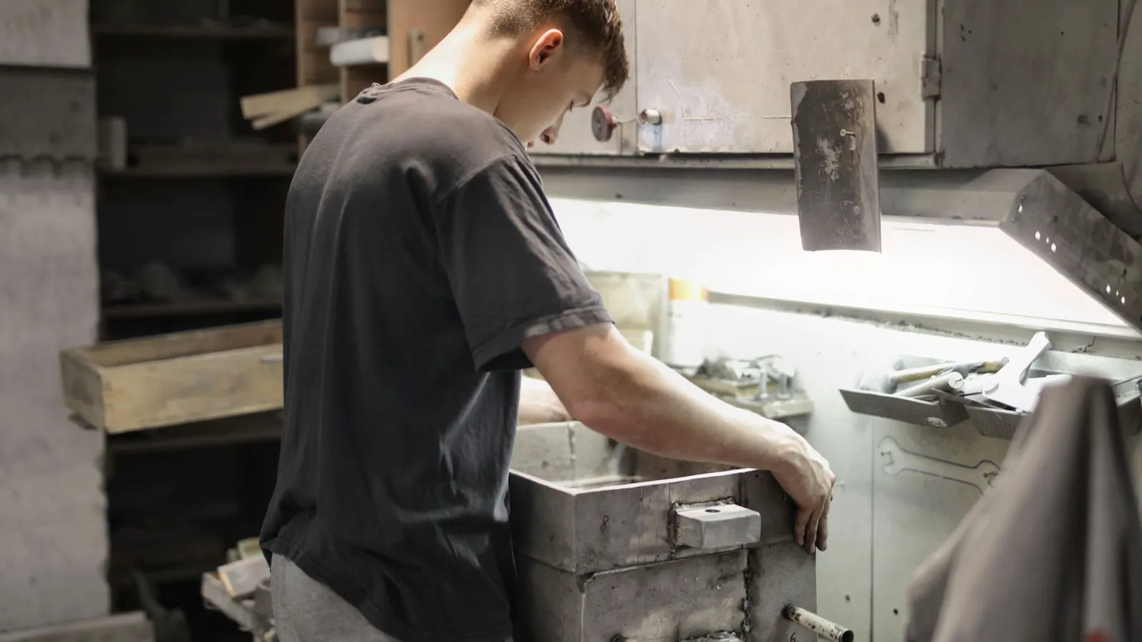
Specify die casting machining tolerances by matching tolerances to casting material behavior, fixture capability, and inspection methods. This guide walks engineers through a step-by-step process for defining realistic post casting operations and part specs without over-machining.
- Match machining tolerances to the machine capability of the chosen post casting operations, not just the drawing need.
- Define hold-down features and reference datums early to reduce fixturing errors and scrap rates.
- Use a tolerance stack-up analysis to verify that cumulative errors remain within functional limits.
- Confirm that the selected inspection method can reliably detect the specified tolerance before release.
Why Tolerance Specification Drives Post Casting Cost
Machining die castings is not a simple subtraction of material from a rough shape. Every tolerance you specify on a drawing adds direct cost to the post casting operations. A tighter tolerance increases tool wear, extends cycle time, and raises the risk of scrap. It also changes the required fixture design and inspection plan.
Engineers often treat machining tolerances as a default. They apply a standard tolerance to every feature, regardless of function. This approach inflates cost and creates unnecessary rework. The goal is to specify the tightest tolerance that the part can function with, while staying within the practical limits of the material and the machine.
This guide provides a step-by-step method for specifying tolerances for die castings. It covers the prerequisites, the core steps, and the verification process. It is designed for engineers working on aluminum, magnesium, or zinc die cast parts that require secondary operations.
Prerequisites: What You Need Before You Start
Before you draw a tolerance on a part, you need three inputs.
- The material behavior of the die casting.
- The available post casting operations and machine capability.
- The functional requirements of the assembly.
Material behavior matters because die cast metals do not machine like steel. Aluminum die castings are soft and work harden quickly. Magnesium is lighter and more reactive. Zinc requires specific tooling and cutting speeds. Each material has a practical limit on how much material you can remove per pass before the tool chatters or the surface finish degrades.
Machine capability is defined by the specific post casting operations you will use. A standard three-axis CNC mill has different capabilities than a multi-axis center. A turning center handles round features differently than a milling head. You must know the machine’s repeatability and the fixture’s rigidity before you commit to a tolerance.
Functional requirements are the baseline. You need to know what the part does. If a bearing fits into a housing, the housing diameter is critical. If a surface is a cosmetic panel, the tolerance is loose. Map every feature to its function. This map drives the tolerance selection.
Step 1: Map Features to Function and Classify Tolerance
Create a feature list for the part. For each feature, assign a function: mating, sealing, locating, cosmetic, or none.
This classification drives the tolerance class.
| Feature Type | Typical Tolerance Range | Reason |
|---|---|---|
| Mating (bearing, shaft) | ±0.02 mm or tighter | Fits must be precise to avoid play |
| Locating (datum pin) | ±0.05 mm | Position must be repeatable |
| Sealing (gasket face) | ±0.1 mm | Flatness matters more than size |
| Cosmetic (visible surface) | ±0.5 mm or looser | Visual quality is the standard |
| Non-critical (non-contact) | ±0.5 mm to ±1.0 mm | No assembly interaction |
Do not assume a default. If a feature does not touch another part, do not tighten it. The cost of machining a non-critical feature to ±0.05 mm when ±0.5 mm works is pure waste.
Step 2: Establish a Datum System
Select three primary datums. These are the features that define the part’s position and orientation on the fixture.
Good datums are stable, flat, or cylindrical features that are easy to locate. A large flat face is better than a small pin. A cylindrical bore is better than a sharp corner.
The datum system must be machined first. If you machine a critical hole before establishing the datum, the hole position is relative to the fixture, not the part. This creates positional error.
Choose datums that are easy to inspect. If the datum is on the bottom of the part and the top is machined, the inspector must flip the part. This adds time and error.
Step 3: Define Hold-Down and Fixturing Strategy
The fixture must hold the part without moving during cutting.
For aluminum, a vacuum table or mechanical clamps work well. For magnesium, avoid heat sources that can change the material properties. For zinc, be careful with clamping pressure, as the material is softer and can deform.
The fixture design must account for the material removal. If you remove 2 mm of stock, the part will shift. The fixture must clamp the part after the roughing pass, or the clamps must be positioned to account for the shift.
A common mistake is clamping the part on a flat face that is also a datum. If the clamp pressure distorts the part, the datum moves. The solution is to clamp on a non-critical area or use a fixture that locates on the raw casting shape.
Step 4: Calculate Tolerance Stack-Up
Tolerances do not exist in isolation. When a part has multiple machined features, the errors add up.
Use a tolerance stack-up analysis. Identify the critical path from one datum to another. For example, if you machine two holes and a boss, the distance between the holes depends on the accuracy of both holes and the boss.
If the stack-up exceeds the functional limit, you have two choices. Loosen the individual tolerances and tighten the assembly tolerance, or tighten the individual tolerances to reduce the stack.
Do not stack tolerances on features that are not on the critical path. Only features that affect the assembly interaction matter.
Step 5: Select Cutting Strategy and Tooling
The cutting strategy determines what tolerance is achievable.
A roughing pass removes bulk material. A finishing pass sets the final dimension. The finishing pass should remove a small amount of material, typically less than 0.5 mm. If the finishing pass removes too much, the tool chatters and the surface finish degrades.
Tooling selection is critical. For aluminum, use uncoated tools with a sharp edge. For magnesium, use tools that resist corrosion. For zinc, use tools with a high helix angle to prevent buildup.
The machine must be capable of the feed rate and speed required for the tolerance. A standard mill can hold ±0.1 mm. A high-precision center can hold ±0.02 mm. Match the tooling and machine to the tolerance.
Step 6: Specify Inspection and Acceptance Criteria
The drawing must define how the tolerance is measured.
For a bore, specify the method: bore gauge, plug gauge, or CMM. For a flatness, specify the method: surface plate and feeler gauges, or laser interferometer. For a position, specify the method: CMM or optical comparator.
The inspection method must be capable of the tolerance. If you specify ±0.05 mm but only have a gauge with 0.1 mm resolution, you cannot verify the tolerance. The acceptance criteria must be based on the inspection method capability.
Define the sampling plan. If the part is produced in high volume, inspect every part on critical features. If the part is low volume, inspect a sample. The sampling plan must be documented.
Step 7: Review for Machinability and Cost
Review the drawing with the post casting operations team.
Ask three questions:
- Can the machine hold the specified tolerance on this material?
- Is the fixture design practical for the hold-down?
- Is the inspection method available and capable?
If the answer to any question is no, revise the tolerance or the process.
This review prevents the situation where the drawing is released, the part is machined, and the inspection team finds the part out of tolerance. The cost of a revision after production is higher than the cost of a tighter tolerance before release.
Common Mistakes in Tolerance Specification
Engineers make three common mistakes when specifying tolerances for die castings.
First, they apply a default tolerance to every feature. This inflates cost. A non-critical feature machined to ±0.05 mm when ±0.5 mm works adds cost and risk.
Second, they ignore the material behavior. Aluminum work hardens. If you remove too much material in one pass, the tool dulls and the surface finish degrades. The cutting strategy must account for this.
Third, they do not define the inspection method. A tolerance without a measurement method is not a tolerance. It is a guess.
Final Verification: The Release Check
Before releasing the drawing for production, run a final check.
- Verify that every feature is classified by function.
- Confirm that the datum system is stable and easy to locate.
- Check the tolerance stack-up for the critical path.
- Ensure the inspection method is capable of the specified tolerance.
- Review the cutting strategy for material behavior.
If the drawing passes this check, it is ready for post casting operations. If it fails, revise the drawing before release.
This process is not a one-time task. It is a review. Every time the part design changes, re-run the check. The tolerance specification is a living document that must reflect the current design and the available manufacturing capability.
By following these steps, you set realistic machining tolerances for die casting. You reduce cost. You reduce scrap. You ensure that the part functions as intended.
Frequently asked questions
What is the standard tolerance for die cast machining?
There is no single standard. Tolerances depend on the feature function, the material, and the machine capability. Mating features typically require tighter tolerances than non-critical features.
Can I specify a tolerance tighter than the machine capability?
No. If the machine cannot hold the tolerance, the part will be rejected. Specify a tolerance that the available post casting operations can achieve with the required inspection method.
How does material choice affect machining tolerance?
Material choice affects tool wear, cutting speed, and surface finish. Aluminum work hardens, magnesium is reactive, and zinc is soft. Each material has a practical limit on material removal per pass.
Do I need a tolerance stack-up analysis for every part?
Yes. Any part with multiple machined features requires a stack-up analysis to ensure that cumulative errors remain within functional limits.
Can I use the raw casting as a datum?
You can, but it is risky. The raw casting shape can vary from die to die. It is better to use machined datums that are stable and easy to locate.