Outlook: Future of In-Die Porosity Monitoring Systems
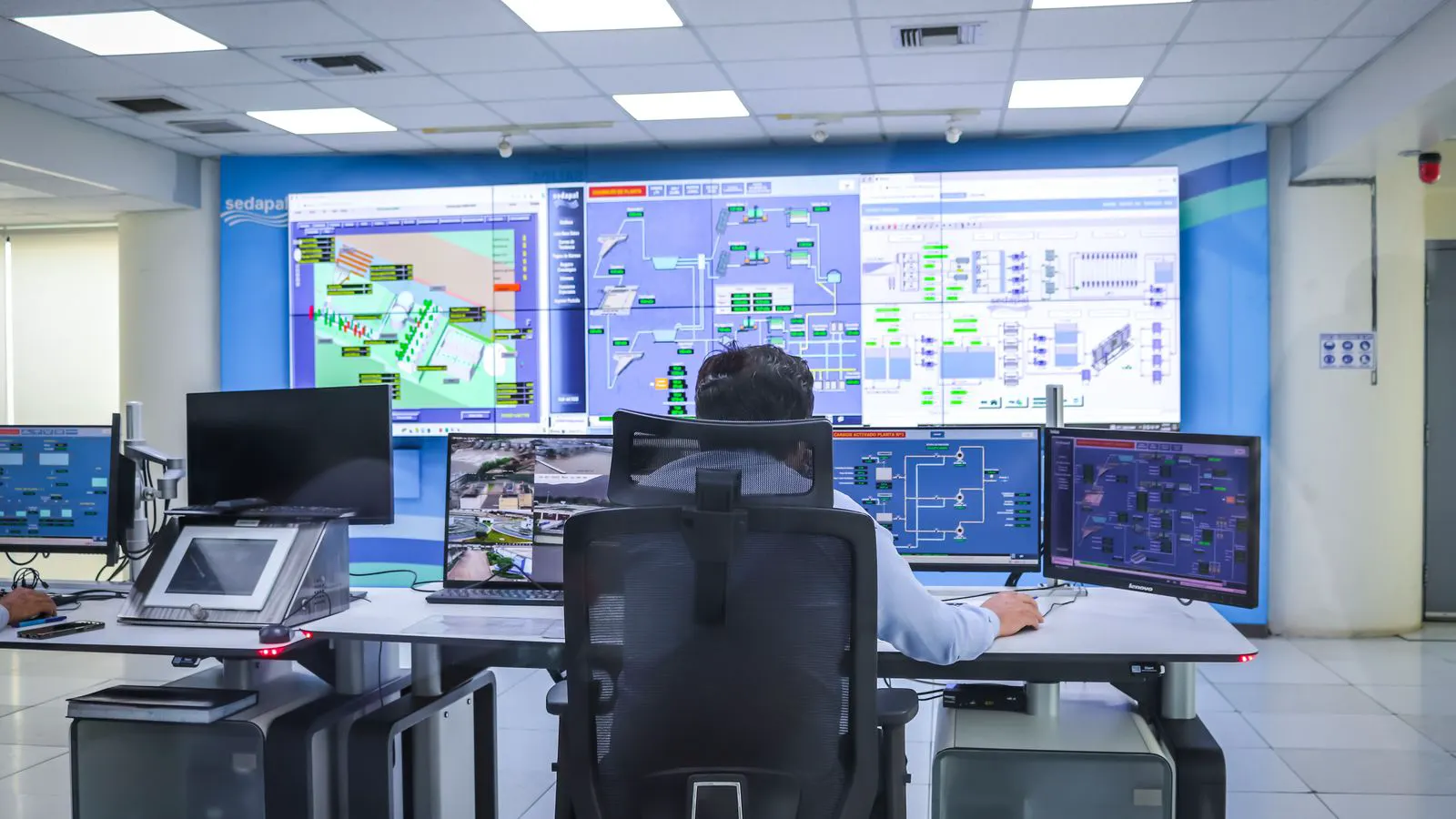
Die casting in-die monitoring is moving from end-of-line inspection to live sensor integration. Buyers should plan for real-time defect detection, automated rejection logic, and data-driven process control. This shift changes how plants manage production quality control and reduce scrap.
- In-die monitoring will shift quality checks from final inspection to live process control
- Buyers should prepare for sensor integration with existing die casting control systems
- Real-time defect detection will reduce scrap and support tighter production quality control
- Data from in-die sensors will drive preventive maintenance and process tuning
Why In-Die Monitoring Is Becoming a Production Priority
End-of-line porosity inspection tells a buyer what failed. In-die monitoring tells them why. The difference matters as casting operations face tighter customer specifications, tighter scrap budgets, and less tolerance for batch-level defects. Real-time defect detection inside the die cavity or at the gate changes the timing of quality control. It moves the check from after the part cools and hardens to the moment the melt fills the cavity.
For many plants, the practical shift is simple: stop sorting good parts from bad parts after the fact. Catch the defect while the die is still open and the process is still adjustable. That requires sensors that can sense pressure, temperature, acoustic signals, or other physical changes during fill and solidification. It also requires a control system that can act on that data.
The technology is not new in principle. Pressure transducers, thermocouples, and acoustic sensors have been used in die casting for decades. What is changing is the integration layer. Sensors are becoming more robust, easier to install, and more compatible with plant control networks. Buyers who watch this space should think in terms of architecture, not just hardware.
What Real-Time Defect Detection Actually Requires
Real-time defect detection is not a single sensor. It is a chain. The first link is measurement. A pressure transducer in the die cavity can detect fill pressure spikes or drops that suggest gas porosity or incomplete fill. A thermal sensor can reveal delayed solidification or hot spots in the die. An acoustic sensor can pick up cavitation or vapor bubble collapse. Each method has strengths and limits.
The second link is interpretation. Raw sensor data is just numbers. The system needs logic that knows what a normal fill looks like for a specific die, material, and part geometry. A pressure curve for a thick aluminum bracket will not match a thin zinc housing. The logic must account for die temperature, shot speed, melt temperature, and cavity geometry. Without that baseline, false alarms become a daily nuisance.
The third link is action. If the sensor detects a porosity event, what happens next? Does the system reject the next part? Does it slow the die? Does it flag the operator? Does it log the event for later review? The action logic determines whether the system improves quality or just adds noise.
The Five to Six Shifts Buyers Should Plan For
Shift 1: From Periodic Checks to Continuous Measurement
Many plants still rely on periodic die cavity checks. A technician inspects the die at the start of a shift, after a mold change, or when porosity complaints arrive. In-die monitoring changes that cadence. The die is measured continuously. The data stream never stops. This requires a different mindset. The die is no longer a passive tool. It is an active sensor node.
Buyers should plan for higher data volume. A single die can generate thousands of data points per hour. The challenge is not collecting the data. The challenge is making it useful. Storage, processing, and display must scale with the number of dies in the plant.
Shift 2: From Single Sensor to Sensor Fusion
No single sensor type covers every defect. Pressure transducers are strong for fill and solidification events. Thermal sensors are strong for die temperature anomalies. Acoustic sensors are strong for void formation and collapse. Gas porosity, shrinkage porosity, and misfeed can look different across these signals. Sensor fusion combines multiple inputs into a single quality decision.
This shift requires more than adding sensors. It requires calibration. The sensors must be aligned in time and space. A pressure spike at one location and a thermal drop at another must be interpreted together. The control system needs to understand the relationship between signals, not just treat them as independent alarms.
Shift 3: From Alarm to Automatic Response
An alarm tells the operator something is wrong. An automatic response fixes something before it becomes a defect. The next step in in-die monitoring is closed-loop control. If the system detects a pressure anomaly, it can adjust shot speed, hold pressure, or die temperature on the next shot. If it detects a thermal drift, it can trigger a die heat adjustment.
This requires confidence in the sensor data and in the control logic. A false trigger can waste material and disrupt production. Buyers should start with advisory mode. Let the system recommend adjustments. Then, once trust is built, allow limited automatic responses. Full autonomous control is possible, but it demands a mature data foundation.
Shift 4: From End-of-Line Sorting to In-Process Rejection
End-of-line inspection often uses X-ray, CT, or dye penetrant. These methods are accurate but slow and expensive. In-die monitoring can reject defective parts before they reach the finishing line. The part is still in the die or at the gate. The rejection decision is immediate. The cost of rejection is low because the part has not been machined, painted, or packed.
This shift changes the economics of quality control. Scrap cost drops. Re-work cost drops. The plant can focus inspection resources on complex parts that still need final verification. For buyers, the payoff is in reduced re-inspection and shorter cycle times.
Shift 5: From Reactive Troubleshooting to Predictive Maintenance
Porosity is not only a process problem. It is often a die problem. Worn die cavities, damaged vents, and thermal fatigue all contribute to defects. In-die sensor data can reveal these issues before they cause a batch of scrap. A gradual pressure drop over several shifts may indicate a vent blockage. A rising thermal baseline may indicate die erosion.
This shift moves maintenance from scheduled to condition-based. The die is maintained when the data says it needs it, not when the calendar says it should. Buyers should plan for a maintenance record that includes sensor history, not just mechanical service logs.
Shift 6: From Plant Data to Customer Data
Customers increasingly ask for traceability. They want to know which die, which shift, and which process parameters produced a specific part. In-die monitoring provides that traceability at the shot level. Each part can be linked to the sensor data that captured its formation. For buyers serving automotive or aerospace customers, this capability is no longer optional. It is a contract requirement.
The data must be stored, organized, and exportable. A single sensor log is not enough. The system must tie the log to the part number, the die, and the shift record. This requires integration with the plant’s existing data systems.
How to Prepare Your Plant for In-Die Monitoring
Audit Your Current Quality Data
Before buying sensors, map what you already know. Where do porosity complaints come from? Which dies produce the most scrap? Which customers demand the tightest specifications? The audit should include die condition, vent design, melt temperature ranges, and shot parameters. This baseline is the reference point for all future monitoring.
Define the Defect You Want to Catch First
Do not try to monitor every defect at once. Pick one. A common starting point is gas porosity at the gate or shrinkage porosity in thick sections. The chosen defect should be measurable with the available sensor types. It should also be costly enough to justify the investment.
Choose a Modular Sensor Architecture
Avoid single-vendor lock-in. The market is moving toward modular systems. Sensors should be swappable. The control software should accept multiple input types. The data output should be open. This flexibility matters as sensor technology improves. A system bought today should still work when better sensors arrive in three or five years.
Plan for Data Integration
In-die monitoring is useless if the data sits in a standalone box. Plan the network path from sensor to control room. Plan the storage. Plan the display. The system should feed into the existing die casting control software, the plant’s data lake, and the customer reporting system. This integration work is often the hardest part of the project.
Train Operators on Data Literacy
The system will only work if operators understand the data. A pressure curve is not just a line. It is a story about fill, venting, and solidification. Operators need to recognize normal and abnormal patterns. They need to know when to trust the system and when to override it. Training should include hands-on review of real sensor logs from the plant’s own dies.
A Practical Comparison of Monitoring Approaches
| Monitoring Approach | Primary Sensor | Best For | Limitation |
|---|---|---|---|
| Pressure-based | Cavity pressure transducer | Fill events, gas porosity | Less sensitive to late solidification defects |
| Thermal-based | Die cavity thermocouple | Die condition, hot spots | Slower response than pressure sensors |
| Acoustic-based | Ultrasonic or contact microphone | Void formation, collapse | Sensitive to die wear and mounting |
| Fusion-based | Multiple sensors | Complex defect patterns | Requires calibration and integration |
What Buyers Should Ask Vendors Before Purchasing
Ask how the system handles false alarms. A system that alarms constantly loses operator trust. Ask how the sensor data is stored and retrieved. A five-year data retention policy matters for customer traceability. Ask how the system integrates with existing die casting controls. A standalone display is not enough. Ask how the software updates. Sensor logic changes as process understanding improves. Ask how the system scales. A solution that works for one die may not work for a line of twelve.
A Final Note on Readiness
The future of die casting in-die monitoring is not a single technology. It is a combination of sensors, logic, integration, and training. Buyers who prepare now will benefit from lower scrap, better traceability, and earlier detection of die problems. The path is incremental. Start with one die, one defect, and one control action. Expand from there.
Frequently asked questions
What is the main benefit of in-die porosity monitoring over end-of-line inspection?
In-die monitoring detects defects while the part is still in the die or at the gate. This allows immediate rejection or process adjustment, reducing scrap cost and re-work.
Can in-die monitoring replace X-ray or CT inspection?
No. In-die monitoring is best for continuous process control. X-ray and CT remain useful for final verification of complex parts or when customer specifications require it.
How long does it take to implement in-die monitoring?
A basic system on a single die can be installed in days to weeks. A full plant integration with data logging and customer reporting takes longer and depends on existing control systems.
What is the biggest mistake buyers make when adopting in-die monitoring?
Treating it as a sensor purchase instead of a system project. Without proper data integration, operator training, and control logic, the system will not deliver value.
Does in-die monitoring work for both aluminum and zinc castings?
Yes. The principles are similar, but the sensor settings and defect patterns differ by material and die type. A solution designed for one material may need adjustment for the other.